Forcing
70 K prescribed wall ramp over 90 days.
 Early access
Tunnelling & Underground Infrastructure
Terra examines coupled thermal, hydraulic and mechanical response around tunnels and underground structures. The recorded N-01 demonstration begins with a generic tunnel section subjected to a 90-day wall-heating history.

Coupled lifecycle
Underground response evolves as excavation, groundwater, support and operational loads change the boundary conditions. Each stage calls for its own case definition and evidence.
Excavation sequence, ground movement, support timing and lining interaction.
Seepage, pore pressure, drainage, geothermal gradients and prescribed thermal loads.
Energy exchange, thermal cycling and specialist operational boundary conditions.
Creep, swelling, deterioration, rehabilitation and long-horizon underground facilities.
These are modelling questions, not completed case claims. The recorded evidence below is limited to N-01.
Recorded evidence, bounded to N-01
N-01 is a prescribed, generic tunnel-heating demonstration. It does not stand in for every construction, operational or long-service underground case.
Recorded case N-01 · 2-D THM demonstration
A quarter-symmetry tunnel section with a prescribed 20 to 90 °C wall ramp, replayed across 39 recorded solver states over 90 days.
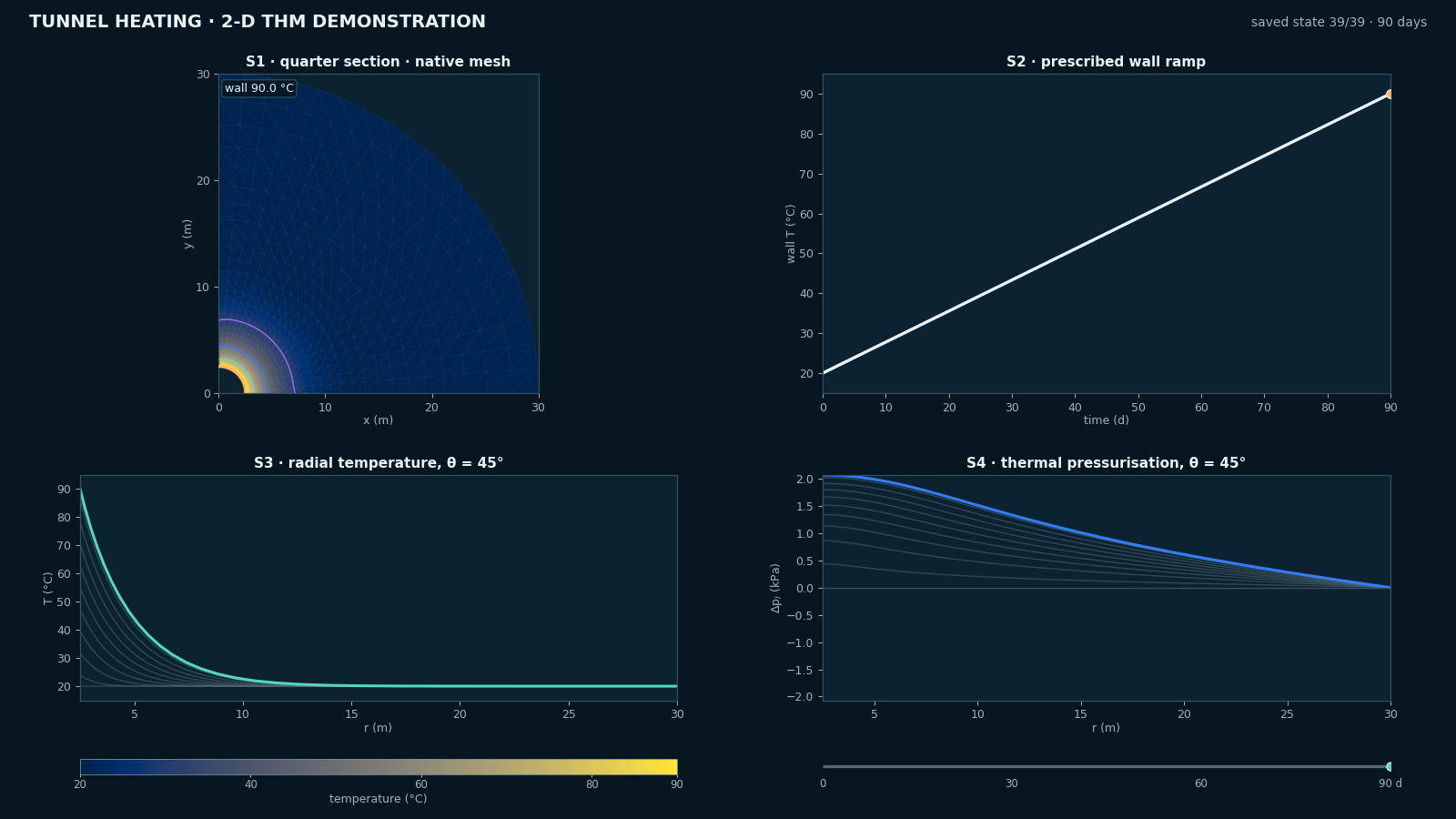
STATE 39 / 39 · DAY 90 days · fixed scales
39 recorded states · no temporal interpolation
Interpretation
70 K prescribed wall ramp over 90 days.
Temperature, flow and deformation in one solve, with liquid pressure and displacement recorded as coupled responses.
Peak thermal overpressure +2.068 kPa and maximum in-plane displacement 1.460 mm. Displacement is not plotted in the four-view plate.
Generic template material set, no repository-specific or site calibration.
Bring an underground case
Share the geometry, ground profile, groundwater regime, construction sequence and thermal or operational history governing your project.